Free PE Mechanical practice exam

Question 1 of 10

Free, right in your browser — 10 exam-real problems for

A wall has an overall heat-transfer coefficient U = 0.10 Btu/h·ft²·°F and an area of 2,000 ft². The indoor-to-outdoor temperature difference is 30°F. The conduction (transmission) heat loss through the wall is most nearly:

Castor— AI tutor

Stuck on the setup? I can give you a hint, check your approach, or point you to the Handbook section.

0 of 10 answered

PE Mechanical exam →

Prefer to read? Browse all 10 HVAC & Refrigeration problems with worked solutions

  1. HVAC & Refrigeration · question 1 of 10

    A wall has an overall heat-transfer coefficient U = 0.10 Btu/h·ft²·°F and an area of 2,000 ft². The indoor-to-outdoor temperature difference is 30°F. The conduction (transmission) heat loss through the wall is most nearly:

    1. A.200 Btu/h
    2. B.6,000 Btu/h
    3. C.60,000 Btu/h
    4. D.600,000 Btu/h
    Answer: B — 6,000 Btu/h

    Transmission load is q = U·A·ΔT (Handbook §5.2.1):

    q = 0.10 × 2,000 × 30 = 6,000 Btu/h
    Why the other options are wrong
    • A.

      Omitted the temperature difference (computed U·A only).

    • C.

      Omitted the U-factor (computed A·ΔT only).

    • D.

      Used the R-value (R = 1/U = 10) in place of U: 10 × 2,000 × 30 = 600,000 Btu/h. The equation uses U, not R.

    Handbook references

    • §5.2.1 — Composite Plane Wall (starts p. 305)
    Look these up in the official NCEES PE Mechanical Reference Handbook ↗
  2. HVAC & Refrigeration · question 2 of 10

    Standard air flows at 2,500 cfm through a round duct 14 in in diameter. The air velocity is most nearly:

    1. A.585 fpm
    2. B.1,840 fpm
    3. C.2,340 fpm
    4. D.9,350 fpm
    Answer: C — 2,340 fpm

    Velocity = flow / area, with A = πd²/4 (d in feet):

    • d = 14/12 = 1.167 ft, A = π(1.167)²/4 = 1.07 ft²
    • V = 2,500/1.07 = 2,340 fpm
    Why the other options are wrong
    • A.

      Used A = πd² (omitted the /4): 2,500/4.28 = 585.

    • B.

      Used A = d² (treated the round duct as square): 2,500/1.36 = 1,840.

    • D.

      Used the radius in πd²/4 (a quarter of the real area): 2,500/0.27 = 9,350.

    Handbook references

    • §9.3.6 — Duct Design — velocity and area (starts p. 489)
    Look these up in the official NCEES PE Mechanical Reference Handbook ↗
  3. HVAC & Refrigeration · question 3 of 10

    A water-cooled centrifugal chiller has a full-load COP of 5.5. Its full-load efficiency expressed in kW per ton is most nearly:

    1. A.0.64
    2. B.1.6
    3. C.2.2
    4. D.5.5
    Answer: A — 0.64

    One ton is 12,000 Btu/hr = 3.517 kW of cooling. kW/ton = electrical input per ton of output = 3.517/COP = 3.517/5.5 = 0.64 kW/ton. (Good centrifugal machines run ~0.5–0.65 kW/ton at full load — a quick sanity range worth memorizing.)

    Why the other options are wrong
    • B.

      Inverted the conversion: 5.5/3.517 = 1.56.

    • C.

      Took 12/5.5 = 2.2 — mixed Btu-based tons with kW without the 3,412 conversion.

    • D.

      Quoted the COP itself.

    Handbook references

    • §4.5.1 — Basic Cycles — COP definitions and 1 ton = 12,000 Btu/hr = 3,516 W (starts p. 289)
    Look these up in the official NCEES PE Mechanical Reference Handbook ↗
  4. HVAC & Refrigeration · question 4 of 10

    Return air at 75°F db / 62.5°F wb (h = 28.1 Btu/lb) mixes with outdoor air at 95°F db / 78°F wb (h = 41.4 Btu/lb) in the ratio 75% return to 25% outdoor. The mixed-air enthalpy (Btu/lb) is most nearly: ____

    Enter your response in the blank.

    Answer: 31.4 Btu/lb (accepts 30.8–32 Btu/lb)

    h_mix = 0.75 × 28.1 + 0.25 × 41.4 = 31.4 Btu/lb. Enthalpy mixes linearly on a mass basis; the ventilation load a system sees is this mixed-air enthalpy relative to the coil leaving condition.

    Handbook references

    • §9.2.3 — Adiabatic Mixing of Two Moist Airstreams (starts p. 481)
    • §7.3 — Psychrometric Charts (humidity-ratio reads) (starts p. 389)
    Look these up in the official NCEES PE Mechanical Reference Handbook ↗
  5. HVAC & Refrigeration · question 5 of 10

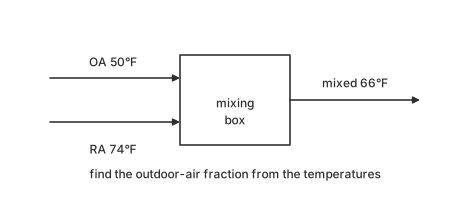
    From the economizer mixing temperatures shown — outdoor air 50°F, return air 74°F, mixed air 66°F — the outdoor-air fraction is most nearly:

    An economizer mixing box: OA 50°F, RA 74°F, mixed 66°F; outdoor-air fraction from the temperatures requested.
    1. A.33%
    2. B.50%
    3. C.67%
    4. D.89%
    Answer: A — 33%

    The mixed temperature is the flow-weighted blend: T_mix = X_OA·T_OA + (1−X_OA)·T_RA.

    Solve: X_OA = (T_mix − T_RA)/(T_OA − T_RA) = (66 − 74)/(50 − 74) = 8/24 = 33%
    Why the other options are wrong
    • B.

      Assumed an equal 50/50 blend rather than computing from the temperatures.

    • C.

      Computed the return-air fraction (66 − 50)/(74 − 50) = 16/24 = 67% — the complement of the outdoor-air fraction.

    • D.

      Took the ratio of the absolute temperatures, 66/74 = 89%, instead of the ratio of temperature differences.

    Handbook references

    • §9.3.2 — Air-Handling Unit Mixed-Air Plenums (starts p. 487)
    Look these up in the official NCEES PE Mechanical Reference Handbook ↗
  6. HVAC & Refrigeration · question 6 of 10

    Which of the following statements of the pump/fan affinity laws are correct? Select the three that apply.

    1. A.Flow varies directly with speed (Q ∝ N)
    2. B.Head (or pressure) varies with the square of speed (H ∝ N²)
    3. C.Power varies with the cube of speed (P ∝ N³)
    4. D.Head varies directly with speed (H ∝ N)
    5. E.Flow varies with the square of speed (Q ∝ N²)
    Answers: A — Flow varies directly with speed (Q ∝ N); B — Head (or pressure) varies with the square of speed (H ∝ N²); C — Power varies with the cube of speed (P ∝ N³)

    The affinity laws: flow ∝ N (A), head ∝ N² (B), power ∝ N³ (C).

    Why the other options are wrong
    • D.

      Head goes with the SQUARE of speed, not directly.

    • E.

      Flow goes DIRECTLY with speed, not the square.

    Handbook references

    • §9.3.8.3 — Fan Affinity Laws (starts p. 522)
    • §3.7.6 — Pump Affinity Laws (starts p. 259)
    Look these up in the official NCEES PE Mechanical Reference Handbook ↗
  7. HVAC & Refrigeration · question 7 of 10

    An energy retrofit costs $28,000 and saves $6,260/yr over 10 years, for which (P/A, 8%, 10) = 6.7101. The retrofit's savings-to-investment ratio (SIR) is most nearly:

    1. A.0.67
    2. B.1.0
    3. C.1.5
    4. D.2.2
    Answer: C — 1.5

    SIR = present value of savings ÷ investment = (6,260 × 6.7101)/28,000 = 42,005/28,000 = 1.50. An SIR above 1.0 means the discounted savings more than repay the investment (equivalent to NPV > 0); federal and institutional energy programs typically fund projects by descending SIR.

    Why the other options are wrong
    • A.

      Inverted the ratio: 28,000/42,005 = 0.67.

    • B.

      Assumed break-even — skipped the arithmetic.

    • D.

      Used UNdiscounted savings: 62,600/28,000 = 2.24 — ignores the time value the SIR exists to capture.

    Handbook references

    • §1.6.2 — Economic Factor Tables (i = 8.00%) (starts p. 50)
    Look these up in the official NCEES PE Mechanical Reference Handbook ↗
  8. HVAC & Refrigeration · question 8 of 10

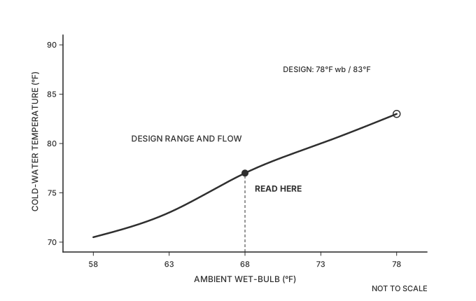
    The cooling tower performance curve shown plots cold-water (leaving) temperature against ambient wet-bulb for the design range and flow. At a 68°F wet-bulb, the tower delivers cold water at most nearly:

    Cooling-tower performance curve on linear axes: AMBIENT WET-BULB (°F) ticked 58, 63, 68, 73, 78 and COLD-WATER TEMPERATURE (°F) ticked 70 to 90 by 5. A solid curve rises left to right and is captioned 'DESIGN RANGE AND FLOW'. An open circle at its right end is called out 'DESIGN: 78°F wb / 83°F'. A dashed vertical at the 68°F wet-bulb given in the stem rises to a filled dot on the curve, tagged 'READ HERE'.
    1. A.68°F
    2. B.73°F
    3. C.77°F
    4. D.83°F
    Answer: C — 77°F

    Enter the curve at 68°F wet-bulb and read up to the design-range line: 77°F leaving water — a 9°F approach at this condition. Tower curves are read exactly this way at off-design wet-bulbs; note the approach widens as wet-bulb falls, which is what limits water-side economizer hours.

    Why the other options are wrong
    • A.

      Water at the wet-bulb itself would need an infinite tower — zero approach is unreachable.

    • B.

      73°F reads the curve at a 63°F wet-bulb — an axis misread one gridline left.

    • D.

      83°F reads the design point (78°F wb) rather than the asked 68°F condition.

    Handbook references

    • §9.3.9 — Cooling Towers and Fluid Coolers — range and approach (starts p. 524)
    Look these up in the official NCEES PE Mechanical Reference Handbook ↗
  9. HVAC & Refrigeration · question 9 of 10

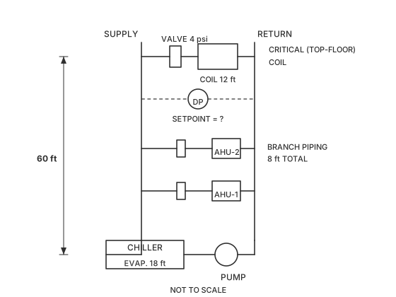
    The variable-flow chilled-water riser shown serves coils on six floors; the critical (top-floor) coil is 60 ft above the pump. At design flow the critical coil has a pressure drop of 12 ft of water, its two-way control valve is sized for 4 psi, and the branch piping to and from the riser loses 8 ft. The chiller evaporator's pressure drop is 18 ft. Using 0.433 psi per ft of water, the minimum differential-pressure setpoint (psi) measured between the supply and return mains at the critical branch takeoff is most nearly:

    Chilled-water riser schematic: chiller and pump at bottom, three coil branches with control valves, critical top coil 60 ft above pump, DP sensor across supply/return mains at the top takeoff.
    1. A.9
    2. B.13
    3. C.20
    4. D.39
    Answer: B — 13

    The DP sensor at the critical takeoff must guarantee just enough differential to push design flow through everything DOWNSTREAM of that point: branch piping + coil + control valve.

    \Delta P = (12 + 8)\ \text{ft} \times 0.433 + 4\ \text{psi} = 8.66 + 4 = 12.7 \approx \mathbf{13\ psi}

    The 60-ft elevation is irrelevant — this is a closed loop, so static height cancels between supply and return. The evaporator drop is upstream of the sensor and is overcome by the pump, not the setpoint.

    Why the other options are wrong
    • A.

      Forgot the control valve: 20\ \text{ft} \times 0.433 = 8.66 \rightarrow 9\ \text{psi} — the valve must still see its design drop at full flow.

    • C.

      Added the chiller evaporator (18 \times 0.433 = 7.8\ \text{psi}): 12.7 + 7.8 = 20.5 — the evaporator is upstream of the sensor.

    • D.

      Added the 60-ft elevation (26\ \text{psi}): static height cancels in a closed loop.

  10. HVAC & Refrigeration · question 10 of 10

    An open-plan office of 12,000 ft² houses 90 occupants (245 Btu/h sensible and 155 Btu/h latent each), with lighting at 0.9 W/ft² and plug loads at 0.5 W/ft². The envelope has a UA of 850 Btu/h·°F at a 20°F outdoor-to-indoor design difference. The 900 cfm of ventilation air arrives 20°F above room temperature and is ducted to the air handler, where it mixes with return air ahead of the cooling coil. The space sensible cooling load (Btu/h) is most nearly:

    1. A.96,000
    2. B.110,000
    3. C.116,000
    4. D.130,000
    Answer: A — 96,000

    The question asks for the SPACE sensible load, so two data items are out of scope: the occupants' latent heat (it is not sensible) and the outdoor-air load (the ventilation air is mixed and cooled at the air handler before it reaches the room, so it is a coil load, not a room load).

    1. People, sensible only:

    q_{\text{people}} = 90 \times 245 = 22{,}050\ \text{Btu/h}

    2. Lighting. The Handbook's lighting heat-gain relation q_{\text{el}} = 3.412\,W F_{\text{ul}} F_{\text{sa}}, with both factors taken as 1.0 and the installed wattage WW = 0.9 W/ft² × 12,000 ft²:

    q_{\text{light}} = 12{,}000 \times 0.9 \times 3.412 = 36{,}850\ \text{Btu/h}
    q_{\text{el}} = 3.412\,W F_{\text{ul}} F_{\text{sa}} · §9.1.3 Electric Lighting (starts p. 447)

    3. Plug loads, the same watts-to-Btu/h conversion:

    q_{\text{plug}} = 12{,}000 \times 0.5 \times 3.412 = 20{,}472\ \text{Btu/h}

    4. Envelope conduction:

    q_{\text{env}} = UA\,\Delta T = 850 \times 20 = 17{,}000\ \text{Btu/h}
    \dot{Q} = UA(T_{\text{inside}} - T_{\text{outside}}) · §5.2.1 Composite Plane Wall (starts p. 305)
    5. Sum:

    q_{\text{space,s}} = 22{,}050 + 36{,}850 + 20{,}472 + 17{,}000 = 96{,}372 \approx \mathbf{96{,}000\ Btu/h}

    Adding the occupants' latent heat (13,950 Btu/h) or the outdoor-air sensible load (19,800 Btu/h) would charge the room with heat it never sees as sensible gain.

    Why the other options are wrong
    • B.

      Added the occupants' LATENT heat (90 \times 155 = 13{,}950) into a sensible total: 110{,}322 Btu/h.

    • C.

      Added the outdoor-air sensible load (1.10 \times 900 \times 20 = 19{,}800), which is removed at the coil, not in the space: 116{,}172 Btu/h.

    • D.

      Added both the occupant latent heat and the outdoor-air load: 130{,}122 Btu/h.