Free PE Power practice exam

Question 1 of 10

Free, right in your browser — 10 exam-real PE Power problems.

A lead-acid station battery is moved from a conditioned control house to an unheated outdoor cabinet at a remote substation. Compared with operation at normal room temperature, what happens in cold weather to the fraction of rated capacity the battery can deliver?

Castor— AI tutor

Stuck on the setup? I can give you a hint, check your approach, or point you to the Handbook section.

0 of 10 answered

PE Power exam →

Prefer to read? Browse all 10 PE Power problems with worked solutions

  1. PE Electrical: Power · question 1 of 10

    A lead-acid station battery is moved from a conditioned control house to an unheated outdoor cabinet at a remote substation. Compared with operation at normal room temperature, what happens in cold weather to the fraction of rated capacity the battery can deliver?

    1. A.It increases, because the lower temperature slows self-discharge inside the cell.
    2. B.It is unchanged, because temperature shifts the terminal voltage but not the ampere-hour capacity.
    3. C.It decreases by the same percentage whatever the discharge current.
    4. D.It decreases, and the shortfall grows as the discharge current rises.
    Answer: D — It decreases, and the shortfall grows as the discharge current rises.

    The published characteristic for this effect is not a single derating number. It is a family of curves of percent of rated capacity against discharge current, one curve per temperature, and reading its SHAPE is what settles the question.

    1 — Which way does temperature move capacity? The curves are ordered by temperature, with normal room temperature sitting in the middle of the family and the higher temperatures lying above it. A cell held below room temperature therefore delivers a smaller fraction of its rated capacity than the same cell in a conditioned room. Cold slows the electrochemistry and raises the internal resistance, so less of the stored charge can be got out before the cell reaches its end voltage.

    2 — Is the loss a fixed percentage? No, and this is the part the shape decides. At a very light load every curve in the family starts near 100 % of rating and the curves lie close together: a battery discharged slowly gives up nearly its full capacity at any of these temperatures. As the discharge current rises, each curve turns down, and the colder ones turn down sooner and more steeply, so the curves fan apart. The penalty for cold is small at a trickle load and large at a heavy one.

    3 — What this means for the substation. The same battery that comfortably carries the station's continuous panel load in an outdoor cabinet may fall well short on a high-current duty such as a switchgear closing operation or a motor-operated disconnect. Sizing a station battery for the coldest expected cabinet temperature at the HIGHEST current the duty draws — not at its average — is what the characteristic is telling the designer to do.

    The correct statement is therefore that the deliverable fraction of rated capacity falls in the cold, and that the shortfall grows with discharge current.

    Why the other options are wrong
    • A.

      Confused shelf life with deliverable capacity. Cold storage does slow the self-discharge of a standing cell, which is why batteries are stored cool, but that is a question about charge lost over weeks of standing. The question here is how much of the stored charge can be got OUT under load, and cold reduces it by slowing the reaction and raising internal resistance.

    • B.

      Treated capacity as a fixed property of the cell and temperature as affecting only the terminal voltage. The published characteristic is plotted as percent of RATED CAPACITY on its vertical axis and separates by temperature, so the ampere-hours obtainable are themselves temperature-dependent; a cold cell reaches its end voltage after delivering fewer ampere-hours, not merely at a different voltage.

    • C.

      Got the direction right but the shape wrong, treating the cold penalty as a single derating percentage. The curves for different temperatures all begin near 100 % of rating at very low discharge current and only separate as the current rises, so a fixed percentage overstates the loss at light loads and badly understates it at heavy ones.

    Handbook references

    • §3.2.1.5 — Relationship of Temperature on Battery Capacity — the printed characteristic of percent of rated capacity against discharge current for a family of increasing temperatures T1 to T6, with T4 identified as normal room temperature (starts p. 34)
    Look these up in the official NCEES PE Electrical and Computer: Power Reference Handbook ↗
  2. PE Electrical: Power · question 2 of 10

    A standby generator is being paralleled onto a generating station's 13.8 kV bus through a synchronizing breaker. Both sides measure 13.8 kV line to line, but the generator phasors lag the bus phasors by 20°. The voltage across each open breaker pole is most nearly:

    1. A.0.48 kV
    2. B.2.77 kV
    3. C.4.79 kV
    4. D.5.45 kV
    Answer: B — 2.77 kV

    One pole of the open breaker has a single bus phase on one side of it and the corresponding generator phase on the other. What stands across it is the phasor difference of those two line-to-neutral voltages — not the difference of two line-to-line values, and certainly not the arithmetic difference of the magnitudes, which is zero here.

    1 — Line-to-neutral magnitude on each side. Both sides are 13.8 kV line to line, and for a wye reference V_L = √3 · V_LN, so

    V_LN = 13,800/√3 = 7,967 V on each side

    2 — Place the two phasors. Take the bus phase-a voltage as the reference:

    V_bus = 7,967∠0° V V_gen = 7,967∠−20° V

    3 — Subtract.

    V_gen = 7,967(cos(−20°) + j sin(−20°)) = 7,486.9 − j2,725.0 V
    ΔV = V_bus − V_gen = 480.5 + j2,725.0 V
    |ΔV| = √(480.5² + 2,725.0²) = 2,767 V ≈ 2.77 kV

    4 — The closed form, as a check. Two phasors of equal magnitude V separated by δ differ by

    |ΔV| = 2 V sin(δ/2) = 2 × 7,967 × sin 10° = 2,767 V

    which agrees exactly, because the two phasors and their difference form an isosceles triangle with apex angle δ.

    What the number means. 2.77 kV is 20 % of nominal standing across an open pole, and it is why a synchro-check relay is set to permit closing only within a few degrees: closing at 20° drives a large transient current through the machine and a shock torque through its shaft. Note also that the two components of the difference are very unequal — 481 V along the reference against 2,725 V at right angles to it. For a small angular separation, the difference between two equal phasors is almost entirely perpendicular to them.

    Why the other options are wrong
    • A.

      Resolved both phasors but then kept only the component of the difference along the reference, V_LN(1 − cos 20°) = 7,967 × 0.0603 = 481 V, discarding the quadrature component. That discarded component is 2,725 V, larger than the one retained by a factor of 5.7. When two equal phasors are separated by a small angle, almost all of their difference lies at right angles to them, so dropping the quadrature part throws away nearly the whole answer.

    • C.

      Carried the line-to-line magnitude straight into the difference, 2 × 13,800 × sin 10° = 4,793 V. A breaker pole is a single-phase gap: it sees the difference of the two line-to-neutral phasors of its own phase, and the line-to-line value is already a difference between two phases on the same side. Using it here overstates the pole voltage by √3, which would also imply an insulation duty the switchgear is not built for at this class.

    • D.

      Used the full separation inside the sine, 2 × 7,967 × sin 20° = 5,450 V, instead of half of it. The two equal voltage phasors and their difference form an isosceles triangle whose apex angle is the 20° separation; dropping a perpendicular from the apex splits it into two right triangles, each subtending 10°, so the difference is 2 V sin(δ/2). Taking sin δ instead makes the answer nearly double at this angle.

    Handbook references

    • §3.1.1 — 3-Phase Circuits — the wye column of the line/phase table, V_L = √3 V_P = √3 V_LN, used to reduce each side's 13.8 kV line-to-line reading to the line-to-neutral phasor a single breaker pole spans (starts p. 25)
    Look these up in the official NCEES PE Electrical and Computer: Power Reference Handbook ↗
  3. PE Electrical: Power · question 3 of 10

    A four-pin resistivity traverse at an industrial site sets four pins in one straight line at 2.5 m spacing. Dry surface soil forces the crew to drive each pin 1.0 m — far deeper than the shallow-pin simplification allows — and the test set indicates 4.50 Ω. The apparent soil resistivity is most nearly:

    1. A.43.3 Ω·m
    2. B.55.2 Ω·m
    3. C.70.7 Ω·m
    4. D.86.6 Ω·m
    Answer: D — 86.6 Ω·m

    The familiar ρ = 2πaR is not a law; it is the equally spaced four-pin relation after the burial depth has been thrown away, and it is only allowed when the pins are driven to l ≤ 0.1a. Here a = 2.5 m, so that limit is 0.25 m and the pins are at 1.0 m — four times too deep. The general form has to be used.

    1 — Assemble the depth-dependent denominator.

    a = 2.5 m l = 1.0 m

    a² + 4l² = 6.25 + 4.00 = 10.25 √ = 3.2016 2a/3.2016 = 1.5617

    a² + l² = 6.25 + 1.00 = 7.25 √ = 2.6926 a/2.6926 = 0.9285

    1 + 1.5617 − 0.9285 = 1.6333

    2 — Apply the general equally spaced four-pin relation.

    ρ = 4πaR / [1 + 2a/√(a² + 4l²) − a/√(a² + l²)]

    4πaR = 4π(2.5)(4.50) = 141.37 Ω·m

    ρ = 141.37/1.6333 = 86.6 Ω·m

    Why the shortcut fails by so much. The simplified form ρ = 2πaR returns 70.7 Ω·m — 18% low. That is not a rounding difference; it is the whole content of the l ≤ 0.1a condition. Driving the pins deep pulls more of the injected current through the shallow soil close to each rod, so the same resistivity registers a lower resistance, and reading it with the shallow-pin form under-reports the earth. On a real traverse the fix is to drive the pins shallower or to widen the spacing until l/a falls back under a tenth; where site conditions rule that out, as they do here, the depth-corrected form is the only defensible reduction.

    Why the other options are wrong
    • A.

      Applied the depth-correcting bracket to the already-simplified form, dividing 2πaR by 1.6333: 70.69/1.6333 = 43.3 Ω·m. The bracket belongs under a numerator of 4πaR, not 2πaR — the simplification to 2πaR is what happens when that bracket collapses to 2, so using both together applies the factor of two twice.

    • B.

      Dropped the subtracted term from the bracket, using 1 + 2a/√(a² + 4l²) = 2.5617 alone: 141.37/2.5617 = 55.2 Ω·m. The bracket has three parts and the third is negative; omitting it inflates the denominator by more than half and pushes the resistivity 36% low.

    • C.

      Used the shallow-pin simplification ρ = 2πaR = 2π(2.5)(4.50) = 70.7 Ω·m. That reduction is valid only for pins driven to l ≤ 0.1a — 0.25 m here — and these pins are at 1.0 m, which is exactly the condition the stem flags. It is the intended reading of the traverse only if the depth is ignored.

    Handbook references

    • §2.1.2 — Ground Resistance Testing — the Equally Spaced 4-Pin Method or Wenner Method, whose printed apparent-resistivity relation ρ = 4πaR/[1 + 2a/√(a² + 4l²) − a/√(a² + l²)] reduces to ρ = 2πaR only where the rods are driven to l ≤ 0.1a, with a the probe spacing and l the burial depth in meters (starts p. 11)
    Look these up in the official NCEES PE Electrical and Computer: Power Reference Handbook ↗
  4. PE Electrical: Power · question 4 of 10

    A ceiling-mounted accent luminaire in a hotel lobby sits 3.6 m above the work plane. Its luminous intensity toward a reception desk is 2,400 candelas, and the desk lies 2.7 m horizontally from the point directly below the luminaire. The horizontal illuminance on the desk is most nearly:

    1. A.95 lx
    2. B.119 lx
    3. C.148 lx
    4. D.185 lx
    Answer: A — 95 lx

    The point method is an inverse-square law with a projection correction, and both parts have to be built from the geometry. The luminaire is not above the desk, so the distance the light travels and the plane the light lands on are two different things.

    1 — The distance the light actually travels. The desk is offset, so the ray is the hypotenuse, not the mounting height:

    D′ = √(3.6² + 2.7²) = √(12.96 + 7.29) = √20.25 = 4.5 m

    2 — The angle from nadir. θ is measured at the luminaire, between straight down and the ray to the desk, so its cosine is the vertical leg over the hypotenuse:

    cos θ = 3.6/4.5 = 0.800 (θ = 36.9°)

    3 — Illuminance normal to the ray.

    I/D′² = 2,400/20.25 = 118.5 lx

    4 — Project onto the horizontal work plane.

    E = (I/D′²)·cos θ = 118.5 × 0.800 = 94.8 ≈ 95 lx

    Intensity in candelas divided by a distance in meters squared gives lux directly, since one candela is one lumen per steradian and one lux is one lumen per square meter.

    The same result follows from the form E = I·cos³θ/D², where D is the mounting height: 2,400 × 0.800³/3.6² = 2,400 × 0.512/12.96 = 94.8 lx. That version folds the slant distance into the cosine — it is the identical relation, not a competing convention, and it is a useful check that the geometry has been handled once and only once.

    A 3.6 m mount reaching 2.7 m off-axis is already at 37° from nadir, where the two corrections together cut the on-axis value nearly in half. That is why an accent luminaire aimed at a specific object has to be located, not just specified.

    Why the other options are wrong
    • B.

      Applied the inverse-square law over the correct slant distance but skipped the cosine: E = 2,400/4.5² = 118.5 lx. That is the illuminance on a surface held perpendicular to the ray — a card tilted to face the luminaire. The desk top is horizontal, and the flux arriving at 36.9° off its normal is spread over a larger footprint, so only cos θ of it counts.

    • C.

      Kept the cosine but used the mounting height in the inverse-square law: E = (2,400/3.6²) × 0.800 = 185.2 × 0.800 = 148.1 lx. The two lengths do different jobs. The distance in the denominator is how far the light traveled, which is the slant distance 4.5 m; the mounting height only enters through the cosine.

    • D.

      Ignored the offset altogether and treated the desk as if it were directly beneath the luminaire: E = 2,400/3.6² = 185.2 lx. This is the illuminance at nadir. Moving 2.7 m off-axis costs both an inverse-square penalty and a projection penalty, and together they take the level down to about half the nadir value.

    Handbook references

    • §2.2.3.2 — Calculations — the point method E = (I/D′²)·cos θ, printed with the nadir/D/D′/θ geometry figure that defines D′ as the slant distance (starts p. 17)
    Look these up in the official NCEES PE Electrical and Computer: Power Reference Handbook ↗
  5. PE Electrical: Power · question 5 of 10

    A 34.5 kV substation served from the transmission system delivers 12 MVA to a plant at 0.78 power factor lagging. A shunt capacitor bank is to be added at the substation bus to raise the power factor to 0.93 lagging with the real load unchanged. The bank rating required is most nearly:

    1. A.3.8 MVAR
    2. B.4.9 MVAR
    3. C.7.5 MVAR
    4. D.11.2 MVAR
    Answer: A — 3.8 MVAR

    A capacitor bank changes the reactive power a load draws from the system; it does not change the real power. So the quantity that stays fixed through the correction is P, and the bank supplies the difference between the reactive power the load needs and the reactive power the system will still deliver.

    1 — Real power, which is what the relation is built on.

    P = S·pf₁ = 12 MVA × 0.78 = 9.36 MW

    2 — The two power angles.

    Φ₁ = cos⁻¹(0.78) = 38.74° tan Φ₁ = 0.8023
    Φ₂ = cos⁻¹(0.93) = 21.57° tan Φ₂ = 0.3952

    3 — The change in reactive power (Handbook §5.1.3):

    ΔP_reactive = P(tan Φ₁ − tan Φ₂) = 9.36(0.8023 − 0.3952)
    = 9.36 × 0.4070 = 3.81 MVAR

    A 3.8 MVAR bank is therefore required.

    Two checks a designer makes without redoing the arithmetic. Before correction the load draws Q₁ = 9.36 × 0.8023 = 7.51 MVAR; after correction it draws Q₂ = 9.36 × 0.3952 = 3.70 MVAR from the system, and 7.51 − 3.70 = 3.81 MVAR is what the bank must make locally. And the corrected apparent power falls to 9.36/0.93 = 10.06 MVA, a 16% reduction in the current the substation transformer and the incoming line carry — which is the reason the bank is installed.

    Why the other options are wrong
    • B.

      Used the apparent power in place of the real power: 12(0.8023 − 0.3952) = 4.88 MVAR. The tangent relation is written on P, not on S — tan Φ is the ratio of reactive to REAL power, so multiplying it by 12 MVA inflates the bank by 1/0.78.

    • C.

      Corrected all the way to unity instead of to 0.93: Q₁ = 9.36 × 0.8023 = 7.51 MVAR. That is the load's entire reactive demand, and it is the answer to a different question. Correcting to 0.93 deliberately leaves 3.70 MVAR flowing in from the system.

    • D.

      Added the two tangent terms instead of subtracting them: 9.36(0.8023 + 0.3952) = 11.21 MVAR. That is the bank size needed to swing the plant from 0.78 lagging all the way to 0.93 LEADING; the stem specifies 0.93 lagging, and overcorrecting to that extent would raise the bus voltage well beyond what the utility permits.

    Handbook references

    • §5.1.3 — Power Factor Correction and Voltage Support — the required change in reactive power to move the power angle from Φ₁ to Φ₂, ΔP_reactive = P_real(tan Φ₁ − tan Φ₂) (starts p. 58)
    Look these up in the official NCEES PE Electrical and Computer: Power Reference Handbook ↗
  6. PE Electrical: Power · question 6 of 10

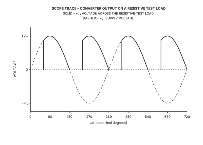
    A technician commissioning a data center battery charger puts an oscilloscope across its resistive test load and captures the trace shown. The charger is fed from a 230 V, 50 Hz single-phase supply, and the test load carries no filter capacitor. The arrangement that produced this waveform is:

    Oscilloscope-style plot titled SCOPE TRACE - CONVERTER OUTPUT ON A RESISTIVE TEST LOAD. The horizontal axis is ωt in electrical degrees, ticked and labeled at 0, 90, 180, 270, 360, 450, 540, 630 and 720, so two complete supply cycles are shown. The vertical axis is labeled VOLTAGE and carries only three tick labels, −Vₘ, 0 and +Vₘ; there is no numeric scale. A dashed horizontal line marks zero across the full width. A legend reads: SOLID = vₒ, VOLTAGE ACROSS THE RESISTIVE TEST LOAD; DASHED = vₛ, SUPPLY VOLTAGE. The dashed curve is a full sinusoid of amplitude Vₘ, rising from zero at 0°, peaking at +Vₘ at 90°, crossing zero at 180°, reaching −Vₘ at 270°, back to zero at 360°, and repeating identically through the second cycle. The solid curve is the load voltage and is never negative. It sits flat on zero from 0° to 60°, then jumps vertically up onto the supply sinusoid at 60°, follows it to the peak +Vₘ at 90° and back down to zero at 180°. It then sits flat on zero again from 180° to 240°, jumps vertically up at 240° to the magnitude of the supply at that instant, rises to +Vₘ at 270° and falls back to zero at 360°. The same pair of pulses repeats in the second supply cycle, with the flat zero intervals running 360°–420° and 540°–600° and the pulses running 420°–540° and 600°–720°. So the load carries two positive pulses per supply cycle, one in each half cycle, each one beginning 60° after the supply's zero crossing with an abrupt vertical rise and ending by decaying smoothly to zero at the next zero crossing. No firing angle, voltage magnitude or time value is annotated anywhere on the drawing.
    1. A.A phase-controlled thyristor bridge feeding the load.
    2. B.An uncontrolled four-diode bridge feeding the load.
    3. C.A single thyristor in a half-wave circuit feeding the load.
    4. D.A triac ac voltage controller in series with the load.
    Answer: A — A phase-controlled thyristor bridge feeding the load.

    Three independent features of the trace each rule out one of the wrong arrangements, and only one arrangement survives all three.

    1 — Count the pulses against the dashed supply trace. The load carries one pulse in the first half cycle and another in the second, two per supply cycle. Both half cycles of the supply therefore reach the load, so the circuit is full-wave. A single-device half-wave circuit delivers one pulse per cycle and would leave a whole half cycle blank.

    2 — Look at where each pulse begins and where it ends. Every pulse starts flat on zero, jumps vertically onto the supply sinusoid 60° after the supply's zero crossing, and then decays smoothly back to zero at the next crossing. A diode conducts the instant it becomes forward-biased, which is the zero crossing; the only way to hold conduction off for part of a half cycle is to gate the device. The dead interval at the start of each half cycle is therefore the firing delay of a controlled device, not diode behavior. The smooth ending at the zero crossing is the resistive load turning the device current off by itself.

    3 — Check the polarity of every pulse. All four pulses are positive. A converter that merely chops the supply and passes it through leaves the negative half cycles negative; an all-positive output means the supply has been rectified.

    Full-wave, gated, rectified: a phase-controlled thyristor bridge.

    One honest qualification. On a purely resistive load, a fully controlled bridge with four thyristors and a half-controlled bridge with two thyristors and two diodes produce the same output waveform — a resistive load cannot distinguish them, because the load current falls to zero at the crossing either way and neither bridge can drive the output negative. The trace identifies the family, not the device count, which is why the answer names the arrangement rather than the number of thyristors in it. Put an inductive load on the same two bridges and they separate immediately: the fully controlled bridge can push its output negative and invert, the half-controlled bridge cannot.

    Why the other options are wrong
    • B.

      An uncontrolled four-diode bridge would produce two pulses per cycle, matching the trace on that count alone, but each diode conducts from the moment it is forward-biased — the supply zero crossing. Its output is an unbroken train of half-sine humps with no dead interval anywhere. The trace sits flat on zero for the first 60° of every half cycle, and nothing an uncontrolled device does can create that gap.

    • C.

      A single thyristor in a half-wave circuit does produce the delayed, abrupt-rising pulse shape shown, so the pulse profile alone fits. It delivers one pulse per supply cycle, though, leaving a full half cycle at zero. The trace shows two pulses in each cycle of the dashed supply waveform, so this arrangement accounts for only half of what is on the screen.

    • D.

      A triac ac voltage controller chops each half cycle at a firing delay, which reproduces both the dead interval and the abrupt rise. It is connected in series with the load and passes the supply straight through, so its load voltage is positive on one half cycle and negative on the next. Every pulse on the trace is positive, so the arrangement rectifies as well as gates, which a series ac controller cannot do.

    Handbook references

    • §3.2.2.1 — AC-DC Converters — Controlled single-phase full-wave rectifier, the four-thyristor bridge with V₀ = (V_m/π)(1 + cos α) (starts p. 35)
    • §3.2.2.1 — AC-DC Converters — Controlled single-phase half-wave rectifier, whose printed output waveform shows conduction beginning at the firing angle α and one output pulse per supply cycle (starts p. 35)
    Look these up in the official NCEES PE Electrical and Computer: Power Reference Handbook ↗
  7. PE Electrical: Power · question 7 of 10

    A 30 m × 30 m substation ground grid in uniform 250 Ω·m soil has a grid-alone resistance of 3.8 Ω and a mutual resistance of 2.6 Ω to its bed of twelve 9.0 m rods, 19 mm in diameter, for which the geometry constant K₁ is 1.37. The combined resistance to earth is most nearly:

    1. A.1.80 Ω
    2. B.2.66 Ω
    3. C.3.08 Ω
    4. D.5.15 Ω
    Answer: C — 3.08 Ω

    Step 1 — get the resistance of the rod bed on its own. The rods are not independent electrodes: each one drives current into earth that the others also have to push against, so the group is worse than n identical rods in parallel. The printed expression for the resistance of all ground rods carries that coupling in its last term (Handbook §2.2.6.5):

    R₂ = (ρ_a / 2nπl₂) · [ ln(8l₂/d₂) − 1 + 2K₁(l₂/√A)(√n − 1) ]

    with ρ_a = 250 Ω·m, n = 12, l₂ = 9.0 m, d₂ = 0.019 m, A = 30 × 30 = 900 m², and K₁ = 1.37 given.

    ρ_a / (2nπl₂) = 250 / (2 × 12 × π × 9.0) = 250 / 678.58 = 0.36841 Ω
    ln(8l₂/d₂) = ln(8 × 9.0 / 0.019) = ln(3,789) = 8.240
    l₂/√A = 9.0 / 30 = 0.300
    2K₁(l₂/√A)(√n − 1) = 2(1.37)(0.300)(√12 − 1) = 2(1.37)(0.300)(2.4641) = 2.0255
    R₂ = 0.36841 × (8.240 − 1 + 2.0255) = 0.36841 × 9.2655 = 3.41 Ω

    Step 2 — combine the grid and the rod bed, mutual resistance included. Two electrodes that share the same volume of earth are not in parallel, because the current from each raises the potential of the other. The printed combination is (Handbook §2.2.6.5):

    R_g = (R₁R₂ − R₁₂²) / (R₁ + R₂ − 2R₁₂)
    numerator = 3.8 × 3.4135 − 2.6² = 12.971 − 6.760 = 6.211
    denominator = 3.8 + 3.4135 − 2(2.6) = 2.0135
    R_g = 6.211 / 2.0135 = 3.08 Ω

    Answer: most nearly 3.08 Ω.

    Two checks the result has to pass. First, adding electrodes can only lower the resistance, so R_g must be below the grid's own 3.8 Ω — it is, by 19%. Second, R_g must also be below the rod bed's own 3.41 Ω, and it is. But it is nowhere near the 1.80 Ω a parallel combination would give, and that gap is the physics of the problem: the rods are driven inside the grid's own footprint, into earth the grid has already raised in potential, so most of what each electrode could do on its own is already being done by the other. That is what R₁₂ = 2.6 Ω measures, and it is large — two thirds of the grid's own resistance.

    Why the coupling term inside R₂ matters too. Drop it and the twelve rods behave as twelve independent electrodes in parallel: a single 9.0 m rod in 250 Ω·m soil is (250/2π × 9.0)(8.240 − 1) = 32.0 Ω, and 32.0/12 = 2.67 Ω. That is 22% below the coupled value, and it propagates straight into the combination. Coupling appears twice in this problem — once among the rods and once between the rods and the grid — and each has its own term.

    Why the other options are wrong
    • A.

      Combines the two electrodes in parallel and drops the mutual resistance entirely: R₁R₂/(R₁ + R₂) = 3.8 × 3.4135 / (3.8 + 3.4135) = 12.971/7.2135 = 1.80 Ω. The rod value is computed correctly; only the combination is wrong. Two electrodes in parallel would each have to be driving into earth the other does not touch, which is exactly what a rod bed inside a grid's own footprint is not doing. The stem supplies R₁₂ = 2.6 Ω precisely because it is not negligible — it is two thirds of the grid's own resistance — and an answer of 1.80 Ω claims the rods almost halve the station's ground resistance when in fact they improve it by 19%.

    • B.

      Treats the twelve rods as twelve independent electrodes in parallel by dropping the coupling term 2K₁(l₂/√A)(√n − 1) from the rod-bed expression. That gives R₂ = 0.36841 × (8.240 − 1) = 2.667 Ω — identical to a single rod's 32.0 Ω divided by twelve — and combining that with the grid gives (3.8 × 2.6673 − 6.76)/(3.8 + 2.6673 − 5.2) = 3.376/1.2673 = 2.66 Ω. The mutual term between grid and rods has been kept and the mutual behavior among the rods themselves has been discarded, so the answer understates the true resistance by 14%. The near-equality of the two 2.66 values is a coincidence of these numbers, not a check.

    • D.

      Uses the combination with R₁₂ in the numerator left unsquared: (3.8 × 3.4135 − 2.6)/(3.8 + 3.4135 − 5.2) = 10.371/2.0135 = 5.15 Ω. The slip is easy to make because R₁₂ appears squared in the numerator and unsquared in the denominator of the same expression. The result fails the first sanity check available: 5.15 Ω is higher than the 3.8 Ω the grid achieves on its own, so driving twelve ground rods would have made the station's grounding worse, which no arrangement of additional electrodes in the same soil can do.

    Handbook references

    • §2.2.6.5 — Schwarz's Formula — the total resistance of a system combining a horizontal grid with vertical rods, R_g = (R₁R₂ − R₁₂²)/(R₁ + R₂ − 2R₁₂), together with the printed expression for R₂, the resistance of all ground rods, and the nomenclature defining ρ_a, n, l₂, d₂, A and K₁ (starts p. 22)
    Look these up in the official NCEES PE Electrical and Computer: Power Reference Handbook ↗
  8. PE Electrical: Power · question 8 of 10

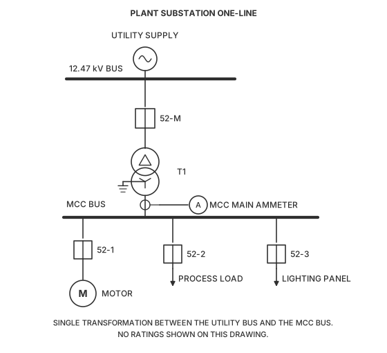
    The plant one-line shown is fed from a 12.47 kV utility bus, where the study base of 1,000 kVA, 12.47 kV is declared. Transformer T1 is nameplate 1,500 kVA, 13.8 kV – 480 V. The MCC main ammeter reads 640 A. In per unit on the study base, that current is most nearly:

    One-line diagram headed PLANT SUBSTATION ONE-LINE, carrying no ratings anywhere on the drawing. At the top a circle containing a tilde, labeled UTILITY SUPPLY, connects downward to a heavy horizontal bus bar labeled 12.47 kV BUS at its left end. A single conductor leaves the middle of that bus and runs down through a square circuit-breaker symbol labeled 52-M, and on into the primary of a two-winding transformer labeled T1, drawn as two interlocking circles with a delta triangle inside the upper winding and a grounded-wye glyph inside the lower winding. A conductor leaves the transformer secondary and runs down to a second heavy horizontal bus bar labeled MCC BUS at its left end. On that conductor, between the transformer secondary and the MCC bus, sits a current-transformer circle whose secondary lead runs right into a bubble marked A, labeled MCC MAIN AMMETER. Three feeders hang below the MCC bus: at the left a breaker labeled 52-1 down to a circle containing M, labeled MOTOR; in the middle a breaker labeled 52-2 down to a downward arrow labeled PROCESS LOAD; at the right a breaker labeled 52-3 down to a downward arrow labeled LIGHTING PANEL. A note beneath reads that there is a single transformation between the utility bus and the MCC bus, and that no ratings are shown on the drawing.
    1. A.0.321 per unit
    2. B.0.481 per unit
    3. C.0.532 per unit
    4. D.0.589 per unit
    Answer: B — 0.481 per unit

    Per-unit work is base bookkeeping. The base apparent power is common to the whole network, but the base voltage changes at every transformer — and it changes by the transformer's NAMEPLATE TURNS RATIO, not by whatever the buses are nominally called.

    1 — Base voltage in the MCC zone. The base is declared as 12.47 kV in the utility zone. T1 is wound 13.8 kV to 480 V, so it steps by 0.48/13.8:

    base kV at the MCC = 12.47 × (0.48/13.8) = 0.4337 kV

    It is not 0.48 kV. A 13.8 kV-rated transformer energized from a 12.47 kV system delivers proportionally less on the secondary, and the base has to follow the winding, not the label on the bus.

    2 — Base current in the MCC zone. For a three-phase system,

    I_base = base kVA_3φ/(√3 · base kV_LL) = 1,000/(1.732 × 0.4337) = 1,331 A

    3 — Per-unit current.

    I_pu = 640/1,331 = 0.481 per unit

    Check from the other end. The same answer must come out of an apparent-power ratio. The load is √3 × 0.4337 kV × 640 A = 481 kVA, and 481/1,000 = 0.481 per unit. Per-unit current and per-unit apparent power are equal when the per-unit voltage is 1.0, which is what the measured current implies here.

    Plausibility. 481 kVA through a 1,500 kVA transformer is about 32% loading — a normal daytime figure for a plant MCC, and comfortably inside the unit's rating.

    Why the other options are wrong
    • A.

      Took the base apparent power from T1's nameplate, 1,500 kVA, instead of the declared study base of 1,000 kVA: I_base = 1,500/(1.732 × 0.4337) = 1,997 A and 640/1,997 = 0.321 per unit. A study base is chosen once for the whole network and every element is converted onto it; an equipment rating is a base only for that equipment's own nameplate impedance.

    • C.

      Used 0.48 kV as the base voltage in the MCC zone because the transformer is wound for 480 V: I_base = 1,000/(1.732 × 0.48) = 1,203 A and 640/1,203 = 0.532 per unit. Base voltages propagate through the transformer's turns ratio from the zone where the base was declared. Since the base was declared as 12.47 kV and the primary winding is rated 13.8 kV, the secondary base is 12.47 × (0.48/13.8) = 0.4337 kV.

    • D.

      Applied the base transfer the wrong way round, scaling the 480 V winding up by 13.8/12.47 rather than scaling 12.47 kV down by 0.48/13.8: base kV = 0.48 × (13.8/12.47) = 0.5312 kV, giving I_base = 1,087 A and 640/1,087 = 0.589 per unit. The declared base is the 12.47 kV quantity, so it is the one that gets multiplied by the turns ratio.

    Handbook references

    • §3.1.3 — Per Unit System — the 3-phase base set, Base Current, A = Base kVA_3φ/(√3 · Base Voltage, kV_LL) (starts p. 26)
    • §3.1.1 — 3-Phase Circuits — |S| = √3 V_L I_L, used for the apparent-power cross-check on the answer (starts p. 25)
    Look these up in the official NCEES PE Electrical and Computer: Power Reference Handbook ↗
  9. PE Electrical: Power · question 9 of 10

    A starter that inserts a three-phase reactor in series with the stator accelerates a 150 hp, 460 V motor driving a loaded screw conveyor. At rated voltage the motor draws 6.5 times its 180 A full-load current at standstill and develops 160% of full-load torque. The conveyor breaks away at 55% of full-load torque, and plant practice requires 1.25 times that at standstill. At the lowest motor terminal voltage meeting the requirement, the starting line current is most nearly:

    1. A.402 A
    2. B.503 A
    3. C.686 A
    4. D.767 A
    Answer: D — 767 A

    The requirement is a TORQUE, the answer is a CURRENT, and the two do not scale with terminal voltage the same way. Work the torque relation backwards to a voltage first, then carry that voltage across to the current.

    1 — Torque the motor must develop at standstill.

    T_req = 1.25 × 0.55 = 0.6875 of full-load torque

    2 — Terminal voltage that produces it. In the induced-torque expression the terminal voltage appears squared and every other term is a machine constant at a fixed slip, so at standstill T ∝ V₁². At rated voltage the machine develops 1.60 of full-load torque, so

    (V/V_rated)² = 0.6875/1.60 = 0.4297
    V/V_rated = √0.4297 = 0.6555, i.e. 65.6% of rated

    Anything lower fails the requirement, so this is the lowest usable tap.

    3 — Current at that voltage. The reactor is in SERIES with the stator, so one current flows through both — the line current IS the motor current. At standstill the motor impedance is fixed, so that current follows the motor terminal voltage directly, not its square:

    I_LR = 6.5 × 180 = 1,170 A
    I_start = 0.6555 × 1,170 = 766.9 A ≈ 767 A

    Why the starter type is the whole item. A series reactor cuts current in proportion to voltage while cutting torque as its square. An autotransformer starter set for the SAME 65.6% motor voltage would produce the same torque but draw only 0.4297 × 1,170 = 503 A from the line, because it transforms the current a second time. That is choice B, and it is a real starter — just not the one the stem describes. The reactor's compensations are lower cost, a genuinely smooth ramp as the motor's own impedance rises with speed, and a closed transition; the price is a supply current about half again as large for the same starting torque.

    Plausibility. 767 A on a 460 V feeder against a 180 A full-load motor is 4.3 per unit at standstill, a normal reduced-voltage starting draw.

    Why the other options are wrong
    • A.

      Dropped the 1.25 margin AND reduced the current as the square of the voltage: √(0.55/1.60) = 0.5863, and 0.5863²(1,170) = 402 A. Both halves are wrong. The requirement is 1.25 times breakaway, not breakaway itself, and the current through a series reactor falls in proportion to voltage rather than as its square.

    • B.

      Found the correct terminal voltage, 65.6% of rated, and then reduced the line current as its square: 0.4297(1,170) = 503 A. That is the autotransformer relation, in which the current is transformed a second time by the turns ratio. A series reactor carries the motor's own current, so the supply sees the full 0.6555 fraction.

    • C.

      Sized the tap on breakaway torque alone and forgot the 1.25 margin: √(0.55/1.60) = 0.5863, and 0.5863(1,170) = 686 A. At that tap the motor would develop exactly the breakaway torque, leaving nothing to accelerate the conveyor and no allowance for a cold, stiff screw.

    Handbook references

    • §4.2.4 — Electrical Machine Theory — the approximate induced torque T_ind = (3/ω_sync)·V₁²(R₂/s)/[(R₁ + R₂/s)² + (X₁ + X₂)²], whose numerator carries the terminal voltage squared (starts p. 48)
    Look these up in the official NCEES PE Electrical and Computer: Power Reference Handbook ↗
  10. PE Electrical: Power · question 10 of 10

    A 138 kV-13.8 kV delta-wye transformer at a utility substation has a solidly grounded 13.8 kV neutral. A bolted single-line-to-ground fault on the 13.8 kV bus draws 9,000 A. The largest current in the 138 kV line conductors is most nearly:

    1. A.520 A
    2. B.600 A
    3. C.900 A
    4. D.1,560 A
    Answer: A — 520 A

    Step 1 - refuse the shortcut, and know why. The reflex is to scale the fault current by the voltage ratio: 9,000 x 13.8/138 = 900 A. That is correct for a BALANCED fault, where all three windings carry equal currents and everything scales together. A single-line-to-ground fault is not balanced. One secondary winding carries the whole fault current and the other two carry none, so the transformer's connection - not just its ratio - decides what appears on the 138 kV lines. Work through the windings.

    Step 2 - the secondary windings. The secondary is wye, so each winding is in series with its own line conductor and carries that line's current:

    faulted phase winding 9,000 A
    the other two windings 0 A

    Step 3 - cross to the primary windings. The turns ratio is set by the voltage each WINDING sees, not by the two line voltages. A delta winding sees the full 138 kV; a wye winding sees 13.8/sqrt(3) = 7.967 kV:

    a = 138,000 / 7,967 = 17.32

    By the ideal-transformer relation I_primary/I_secondary = N_secondary/N_primary = 1/a, the one energized primary winding carries

    9,000 / 17.32 = 519.6 A

    and the other two primary windings carry nothing.

    Step 4 - cross from the primary windings to the primary lines. In a delta, each line current is the DIFFERENCE of the two winding currents that meet at that corner. With only one winding energized at 519.6 A, the two corners it touches each carry 519.6 A and the third corner carries zero:

    two 138 kV lines 519.6 A
    the third line 0 A

    So the largest current in the 138 kV line conductors is 519.6 A, most nearly 520 A - about 58 percent of what the voltage ratio alone would suggest.

    Step 5 - check it a second way. In sequence terms the secondary carries I_0 = I_1 = I_2 = 9,000/3 = 3,000 A. The delta primary blocks zero sequence, so only the positive- and negative-sequence currents reach the lines, each 300 A after the ratio, and the delta-wye connection shifts them by +30 and -30 degrees. Adding them: 300 angle 30 + 300 angle -30 = 2 x 300 x cos 30 = 519.6 A. The two derivations agree.

    Why this matters for coordination. A primary fuse or relay set from the balanced referral will see only 58 percent of the current the setting assumed, and a device that looked coordinated on a three-phase fault can fail to operate for a secondary ground fault.

    Why the other options are wrong
    • B.

      Removes the zero-sequence current from the fault current and then applies the balanced ratio: I_0 = 9,000/3 = 3,000 A, so 9,000 - 3,000 = 6,000 A is taken as 'what gets through' the delta, and 6,000 x 13.8/138 = 600 A. The first half is a real insight - a delta primary does block zero-sequence current from its lines - but the second half is wrong twice over. Zero-sequence current is not simply subtracted from a phase current; and once the positive- and negative-sequence components are separated they must be recombined with the connection's 30 degree shift, which is what produces 2 cos 30 = 0.866 rather than the 0.667 this route assumes. The route reaches a plausible number by stopping halfway through the right idea.

    • C.

      The balanced referral, applied to an unbalanced fault: 9,000 x 13.8/138 = 900 A. This is the single most likely wrong answer, because it is the correct answer to the question one line up - the primary line current for a THREE-PHASE fault of the same magnitude - and because the arithmetic is one step and looks complete. It ignores the fact that only one secondary winding is energized, which is precisely what the delta connection then redistributes. A candidate can also reach 900 A after correctly finding the 519.6 A winding current, by applying the balanced delta relation I_line = sqrt(3) x I_phase, which holds only when all three windings carry equal currents.

    • D.

      Builds the ratio out of the wrong voltage on the delta side: takes the 138 kV winding voltage as a line-to-neutral value, 138/sqrt(3) = 79.7 kV, and refers with 9,000 x 13.8/79.7 = 1,559 A, most nearly 1,560 A. The error is the mirror image of the correct step: the sqrt(3) belongs on the WYE side, where a winding sees line-to-neutral voltage, and not on the delta side, where a winding sees the full line-to-line voltage and there is no neutral to refer to. A candidate who knows a sqrt(3) enters this problem but attaches it to the wrong winding lands here, and the answer is larger than the balanced referral, which should itself be a warning.

    Handbook references

    • §4.3.1.1 — Single-Phase Transformer Equivalent Circuits - the ideal-transformer relation E1/E2 = I2/I1 = N1/N2 = a, applied per winding to cross from the wye secondary to the delta primary (starts p. 50)
    Look these up in the official NCEES PE Electrical and Computer: Power Reference Handbook ↗